| Turbocharged Systems |
 |
Turbocharger System Components - Exchange
| Advanced NDT inspection services are performed by Victor's NAS-410 National Aerospace Standards certified inspectors in accordance with our FAA approved repair station #BJ399L requirements. |
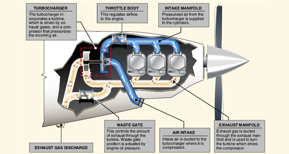
How a Turbo System Works
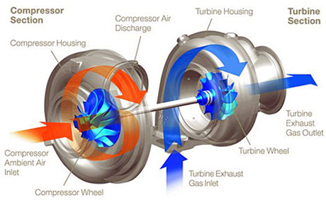
A turbocharger consists of a turbine and a compressor linked by a shared axis. The turbine inlet receives exhaust gases from the engine exhaust manifold causing the turbine wheel to rotate. This rotation drives the compressor, compressing ambient air and delivering it to the air intake of the engine. The objective of a turbocharger is to improve upon the size-to-output efficiency of an engine by solving for one of its cardinal limitations. A naturally aspirated engine uses only the downward stroke of a piston to create an area of low pressure in order to draw air into the cylinder. Since the number of air and fuel molecules determines the potential energy available to force the piston down on the combustion stroke, and because of the relatively constant pressure of the atmosphere, there ultimately will be a limit to the amount of air and consequently fuel filling the combustion chamber. This ability to fill the cylinder with air is its volumetric efficiency.
Since the turbocharger increases the pressure at the point where air is entering the cylinder, and the amount of air brought into the cylinder is largely a function of time and pressure, more air will be drawn in as the pressure increases. The intake pressure, in the absence of the turbocharger determined by the atmosphere, can be controllably increased with the turbocharger. |
|
 |
| Turbocharger Components |
|
Turbo Boost |
| The turbocharger has four main components. The turbine and impeller wheels are each contained within their own conical housing on opposite sides of the third component, the centre hub rotating assembly (CHRA). The housings fitted around the compressor impeller and turbine collect and direct the gas flow through the wheels as they spin. The centre hub rotating assembly houses the shaft that connects the compressor impeller and turbine. It also contains a bearing system to suspend the shaft, allowing it to rotate at very high speed with minimal friction. |
|
Boost refers to the increase in manifold pressure that is generated by the turbocharger in the intake path or specifically intake manifold that exceeds normal atmospheric pressure. Boost pressure is limited to keep the entire engine system including the turbo inside its design operating range by controlling the waste gate, which shunts the exhaust gases away from the exhaust side turbine. |
Waste Gate Assembly
By spinning at high speed the compressor turbine draws in a large volume of air and forces it into the engine. As the turbocharger's output flow volume exceeds the engine's volumetric flow, air pressure in the intake system begins to build, often called boost. The speed at which the assembly spins is proportional to the pressure of the compressed air and total mass of airflow being moved. Since a turbo can spin to RPMs far beyond what is needed, or what it is safely capable of, the speed must be controlled. To control the turbo chargers' speed a variable valve mechanism called a waste gate is installed.
The waste gate is controlled by a pneumatic/hydraulic control system. At take off the waste gate is usually kept open, or nearly so, at sea level to keep from over boosting the engine. As the aircraft climbs, the waste gate is gradually closed, maintaining the manifold pressure at or above sea level. The main function of a waste gate is to allow some of the exhaust to bypass the turbine when the set intake pressure is achieved.
| Waste Gate Controller |
|
Pressure Relief Valve |
| On most modern turbo charged engines, the position of the waste gate is governed by pressure-sensing controller mechanisms coupled to an actuator. Engine oil directed into or away from this actuator moves the waste gate position. On these systems, the actuator is automatically positioned to produce the desired MAP simply by changing the position of the throttle control. |
|
To prevent an engines manifold pressure from exceeding the engine's design limitations, a pressure relief valve assembly is installed in the intake system downstream of the turbocharger compressor on some installations. When the pressures reaches it maximum set limit the valve opens preventing the engine from over boosting. |
|