| Transit Time with Sound |
 |
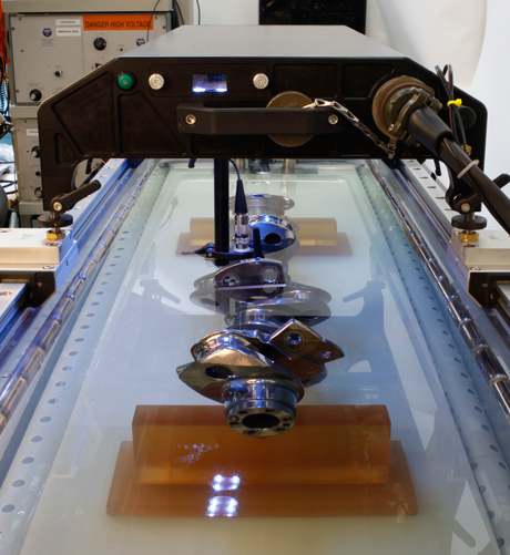
| Crankshaft C-Scan Ultrasonic Testing |
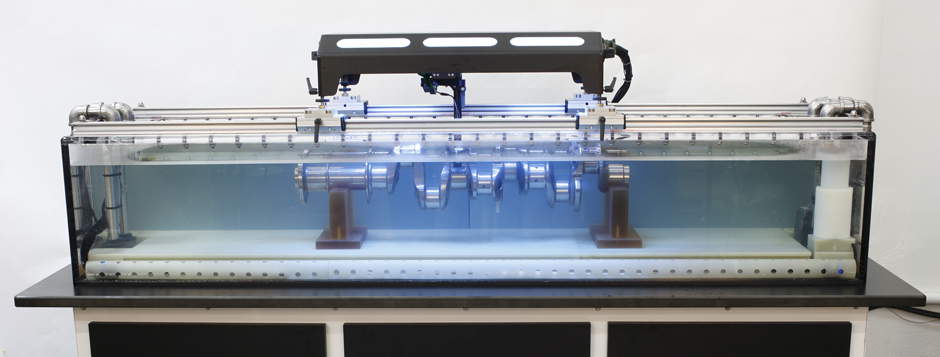 |
| Continental Motors Ultrasonic Inspection of Crankshaft |
C-Scan Presentation
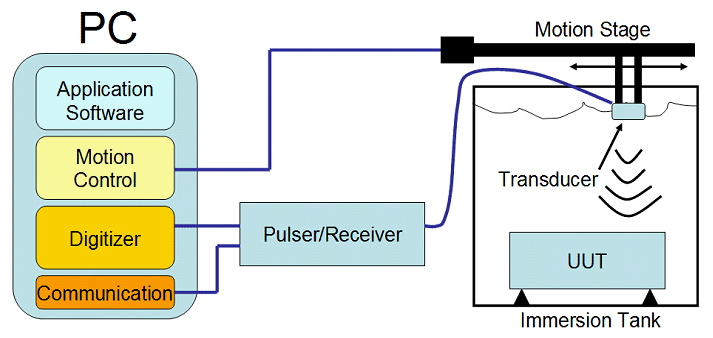
C-Scan presentations provide a plan-type view of the location and size of test specimen features. The plane of the image is parallel to the scan pattern of the transducer. C-Scan presentations are produced with an automated data acquisition system, such as a computer controlled immersion scanning system. Typically, a data collection gate is established on the A-Scan and the amplitude or the time-of-flight of the signal is recorded at regular intervals as the transducer is scanned over the test piece. The relative signal amplitude or the time-of-flight is displayed as a shade of gray or a color for each of the positions where data was recorded. The C-Scan presentation provides an image of the features that reflect and scatter the sound within and on the surfaces of the test piece.
 |
|
 |
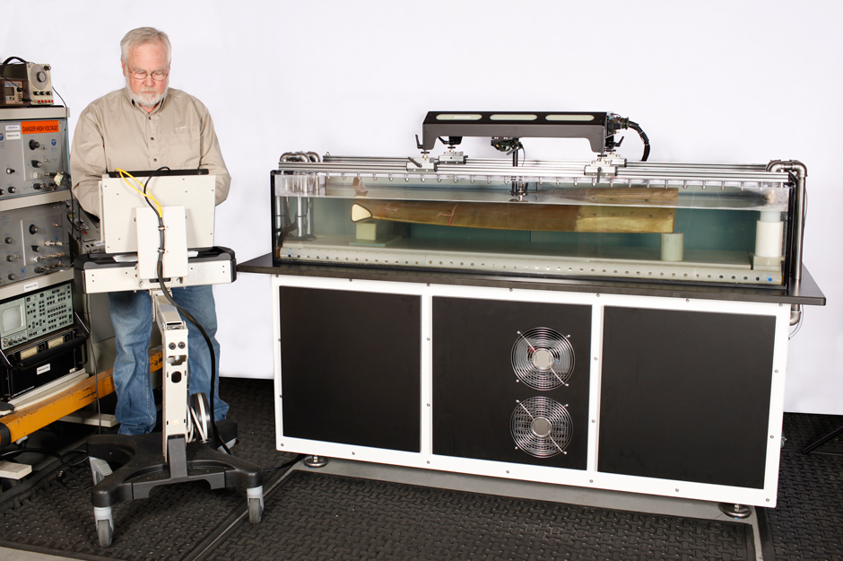
| Carbon Composite Turbine Blade C-Scan Testing |
 |
| Carbon Composite Brakes C-Scan Testing |
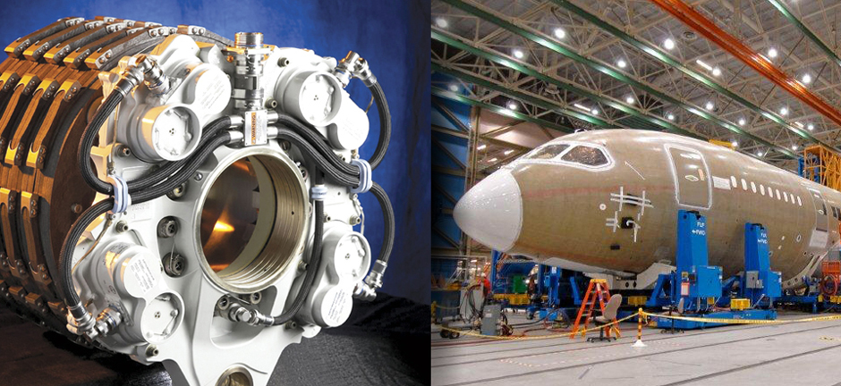 |
| Carbon Composite Brakes |
Boeing Aircraft |
 |
|
 |
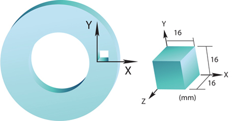
| COMPOSITE ROTOR BRAKE DISK AND SAMPLE SECTION |
|
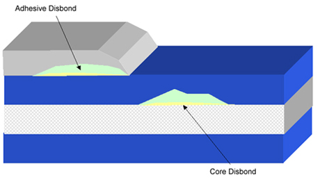
CROSS SECTION OF CARBON COMPOSITE MATERIAL |
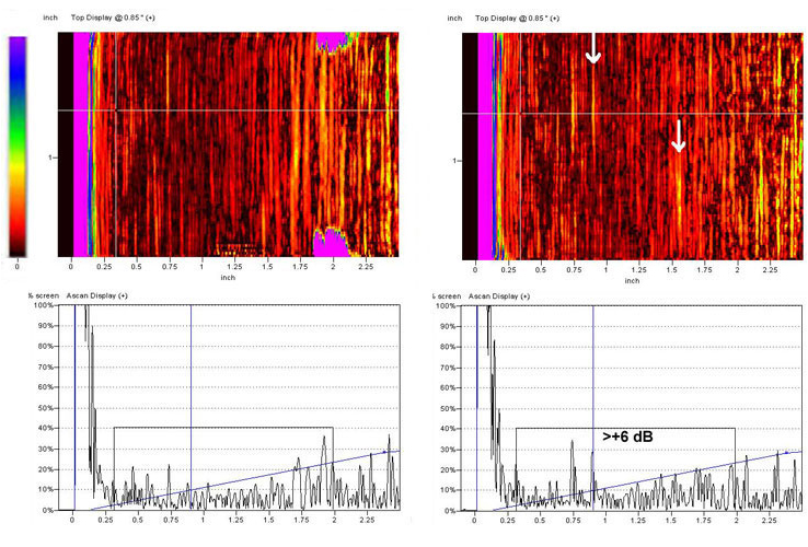
Immersion Ultrasound
C-Scans (Top)
A-Scan (Bottom)
Carbon Composites
By measuring the before and after ultrasonic wave velocities in three directional planes in immersion tests can also identify the characteristics of anisotropy. |
 |
| |
Electromagnetic Acoustic Transmission (EMAT)
Ultrasonic methods of non destructive testing use beams of mechanical waves of short wavelength and high frequency, transmitted from a probe and detected by the same or other probes. An oscilloscope display with a time base shows the time it takes for a ultrasonic pulse to travel to a reflector (a flaw, the back surface or other free surface) in terms of distance travelled across the oscilloscope screen. The height of the reflected pulse is related pulse is related to the flaw size as seen from the transmitter probe. The relationship of flaw size, distance and reflectivity are complex, and a considerable skill is required to interpret the display.
Ultrasonic examination is utilized as a non-destructive testing method to carry out a wide variety of testing tasks enabling Victor Aviation technicians to conduct internal material defect examinations and make measurements of a component. The testing process may be performed in an immersion tank or on the surface of the material to be examined using a couplant and piezoelectric sensors. For applications where a couplant is not desired we use electromagnetic acoustic transmission using EMAT sensors which require no couplant. |
|

|
| |
|
EMAT Sensor on NASA Wind Tunnel Turbine Blade |
| Electromagnetic Acoustic Transduction Principles |
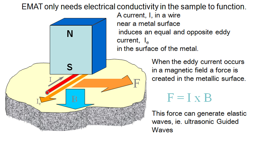 |
The Lorentz Force
The flow of an electric current down a conducting wire is ultimately due to the motion of electrically charged particles (in most cases, electrons) through the conducting medium. It seems reasonable, therefore, that the force exerted on the wire when it is placed in a magnetic field is really the resultant of the forces exerted on these moving charges. |
|
|
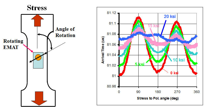
| EMAT BIREFRINGENCE TESTING |
 |
| |
|
|
| |
 |
| EMAT SENSORS INSTALLED ON A WIND TURBINE TRANSMISSION GEAR |
Gear C-Scan Ultrasonic Testing
click on Cscan images
to view larger
|

